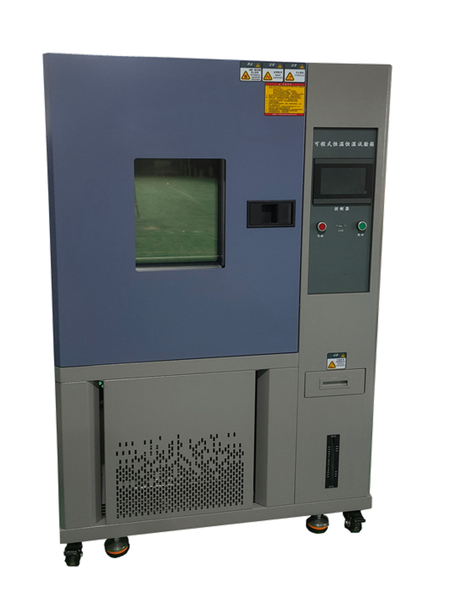
Technical parameters of the constant temperature and humidity test chamber
| 1. Product Name | Programmable constant temperature and humidity test chamber |
| 2. Product model | DT-S-80 (Optional: 100/150/225/408/800/100) |
| 3. Specimen limit | This test equipment prohibits:
(1) Testing or storage of flammable, explosive and volatile substance samples (2) Testing or storage of corrosive substance samples (3) Testing or storage of biological specimens (4) Testing or storage of strong electromagnetic emission source specimens |
| 4. Volume, dimensions and weight | |
| 4.1. Nominal content volume | 80L (Optional: 100L/150L/225L/408L/800L/100L) |
| 4.2. Internal dimensions | Width 400*Height 500*Depth 400mm |
| 4.3. Dimensions | Width 888 * Height 1590 * Depth 880mm |
| 4.4. weight | Approximately 265kg |
| 5. Performance | |
| 5.1. Test environmental conditions
5.2. Test methodology |
The ambient temperature is +25°C, the relative humidity ≤ 85%, and there are no specimens in the test chamber
GB/T5170.2-2008 Temperature Test Equipment GB/T5170.5-2008 Damp heat test equipment (damp heat type only) GB/T2423.1-2008(IEC60068-2-1:2007) Cryogenic test method Ab GB/T2423.2-2008(IEC60068-2-2:2007) High temperature test method Bb GJB 150.3-2008 High temperature test GJB 150.4-2008 Cryogenic test GB/T14710-2009 Environmental requirements and test methods for medical electrical appliances |
| 5.3. Temperature range | -40℃→+150℃ |
| 5.4. Humidity range | (20~98)%RH
(Temperature: 20°C~85°C, refer to the temperature and humidity controllable range chart, no active heat load).
|
| 5.5. Temperature fluctuations | ±0.5℃ |
| 5.6. Humidity fluctuations | ≤2.5% |
| 5.7. Temperature deviation | ≤±2.0℃ |
| 5.8. Humidity deviation | ≤±3% |
| 5.9. Heating time | Average 2~3°C/min (no load) |
| 5.10. Cooling time | Average 0.7~1°C/min (no load) |
| 5.11. Load situation | None |
| 5.12. Operating noise | A sound level≤ 70dB(A)
(Measured in a soundproof room with an ambient temperature of 25 °C and little echo; Using A weighting, the average value of 9 points is tested. Each test point is 1 meter away from the noise source and 1 meter above the ground |
| 5.13. Meet the test standards | (1) GB/T 2423.1-2001 Test A: Low temperature test method
(2) GB/T 2423.2-2001 Test B: High temperature test method (3) GJB 150.3-1986 High temperature test (4) GJB 150.4-1986 Low temperature test (5) IEC68-2-1 Test A: Cold. (6) GB 11158 “Technical conditions for high-temperature test chambers” (7) GB/T 2423.2 “Basic Environmental Test Regulations for Electrical and Electronic Products Test B: High Temperature Test Methods” |
| Structural features | |
| 5.14. Insulation enclosure
|
①Exterior wall material: A3 board spraying
(2) Inner wall material: brushed stainless steel plate SUS#304 . (3) Box insulation material: 100mm high-temperature resistant rigid polyurethane foam (4) Box door insulation material: 100mm high-temperature resistant rigid polyurethane foam |
| 5.15. Bottom structural strength | The bottom of the test chamber is the weight capacity of the track: ≤100Kg/m² (load). |
| 5.16. Air conditioning channels | ①Stainless steel long shaft centrifugal fan: 1 set/90W.
(2) Fan, heater, evaporator (and dehumidifier), drainage device, pressure balance port, adjustable air deflector, temperature sensor |
| 5.17. Test chamber is standard | ①Windows 260x340x40mm 3-layer vacuum tempered glass.
(2) Flat recessed handle, (3) Door hinges: SUS #304进口铰链 (4) Energy-saving lamp in the box: LED energy-saving lamp ⑤Lead hole: φ50mm 1pc |
| 5.18. box door
|
Monolithic door, opening outward, hinge on the left and handle on the right (when facing the front of the cabinet).
(2) Equipped with a safety door locking mechanism (the door can be opened in the test room), the door is equipped with electricity and heat to prevent condensation, and the viewing range of the insulating glass observation window is about (W260×H340mm). The door frame is equipped with an anti-condensation electric heating device |
| 5.19. Control panel | The controller is a touch MNT-600 7-inch display, temperature (humidity) control display, operation indicator, and lighting buttons |
| 5.20. Mechanical room | Refrigeration unit, compressor water tray, pressure discharge device, heating device |
| 5.21. Distribution cabinet | Distribution boards, cooling fans, main power switches, machine tool transformers, intermediate relays, time relays, solid state relays, AC contactors, circuit breakers |
| 5.22. heater | (1) Fin-type heat dissipation tube-shaped stainless steel heater
(2) Heating control mode: SSR (solid state relay) without contacts and equal periodic pulse width adjustment (3) Heating power: about 2KW |
| 5.23. Power cord holes | Located on the back of the cabinet |
| 6. Refrigeration system | |
| 6.1. Hot and cold devices | ①Joint venture with Japan’s Sanyo compressor high-efficiency energy-saving ultra-low temperature refrigeration system(Air-cooled heat dissipation method).
②Cooling method: air cooling |
| 6.2. Heat and cold exchange device | Single-stage refrigeration system, 1 joint venture Japan Sanyo compressor fully enclosed compressor. The ultra-high-efficiency SWEP cold coal cold heat exchange design [made in Sweden (sus#316)] is more efficient than the traditional internal spiral type |
| 6.3. Heating load adjustment | (1) The automatic adjustment of cold coal flow rate device is adopted, which effectively takes away the heating load of the test product and German/Japanese technology
Technique synchronization (2) Compared with the traditional design, the control stability and reproducibility are high, and the super efficiency is more energy-saving and energy-saving |
| 6.4. Refrigeration compressors | Joint venture with Japan’s Sanyo Compressor Fully Enclosed Compressor |
| 6.5. High-efficiency components | (1) The condenser and evaporator adopt AC&R compound spoiler type aluminum fin device
(2) The throttling device adopts imported relaxed refrigeration accessories. |
| 7.6. Expansion System: | Volume-controlled refrigeration system (capillary). |
| 7.7. Evaporative Condenser | All-copper tube heat exchanger. |
| 7.8. Chiller Control Method | (1) The controller of the control system automatically adjusts the operating conditions of the chiller according to the test conditions.
(2) Evaporation pressure regulating valve. (3) Compressor return cooling circuit ② The chiller system is designed with vibration damping and noise reduction measures such as shock absorber tubes |
| 7.9. Refrigerants | Honeywell R404a (ozone depletion index is 0) |
| 8. Electrical control system | |
| a) Controller model | Touch intelligent programmable temperature controller |
| b) Controller specifications | Technical Specifications:
1. 7-inch true color touch thin screen 2. Two control methods: program/value 3. Sensor Type: Two PT100 Inputs (Optional Electronic Sensor Input) 4. Output Mode: Voltage Pulse (SSR) / Control Output: 2 (Temperature/Humidity) / 2 4-20mA Analog Outputs / 16 Relay Outputs (Passive) 5. Control signal: 8 IS control signals/8 T control signals/4 AL control signals 6. Alarm signal: 16 DI external obstacle alarms 7. Temperature measurement range: -90.00°C–200.00°C, (optional -90.00°C–300.00°C) error ±0.2°C; 8. Humidity measurement range: 1.0%–100%RH, error ± 1%RH; 9. Communication interface: (RS232/RS485, communication distance up to 1.2km [optical fiber up to 30km]); 10. Interface language type: Chinese/English 11. Possess the function of Chinese character input; 12. Can be equipped with a printer (USB function optional); 13. A variety of signal combination relay outputs, the signal can be logically calculated (NOT, AND, OR, NOR, XOR), referred to as PLC programming ability; 14. Diversified relay control mode: parameter-> relay mode, relay->parameter mode, logic combination mode, composite signal mode; 15. Program editing: 120 groups of programs can be edited, and each group of programs can be edited with a maximum of 100 segments; |
| 7.3 Controller technical parameters | Accuracy: Temperature±0.1°C+1digit, Humidity±1%R.H+1digit
Resolution: Temperature ±0.01°C, Humidity ±0.1% R.H Temperature slope: 0.1~9.9 can be set. It has the function of upper and lower limit standby and alarm. Temperature and humidity input signal wet and dry bulb PT100x2. 9 sets of P.I.D control parameter setting, P.I.D automatic calculation. Wet and dry ball automatic correction screen |
| 7.4 Control mode | ①Anti-integral saturation PID
②BTC Balanced Temperature Control Mode + DCC Intelligent Cooling Control + DEC Intelligent Electrical Control (Temperature test equipment) ③BTHC balanced temperature and humidity control mode + DCC intelligent cooling control + DEC intelligent electrical control (Temperature and humidity test equipment) |
| 7.4 Screen display function | It adopts the screen dialogue style, no need to press the buttons, and the screen directly touches the options.
Temperature set (SV) and actual (PV) values are displayed directly. It can display the current execution program number, segment, remaining time and cycle count Operation cumulative time function. The temperature program setting value is displayed in a graphical curve, and it has the function of real-time display of program curve execution. With a separate program editing screen, at least 5 segments of temperature, humidity and time can be entered per page. Chinese and English can be switched freely. The fault prompt screen is displayed. The screen can be adjusted for backlight. The on-screen display protection function can be set to timer, timer or manual off. |
| 7.5 Program capacity and control function | Programs that can be used: up to 120 PATTENs.
Usable memory capacity: 12,000 SEGMENTS in total. Repeatable commands: Each command can be executed up to 3200 times. The program is produced in a dialogue format, with functions such as editing, clearing, and inserting. SEGMENTS Time is set to 0~99Hour59Min. Programmable timing control module device x2 sets. It has a power-off program memory, and automatically starts and continues to execute the program function after the power is restored. It has an RS-485 or RS-232 communication interface. The graphical curve can be displayed in real time when the program is executed. It has the function of automatically adjusting the freezing capacity. It has scheduled start and shutdown functions. It has the function of date and time adjustment. Button and screen lock (LOCK) function. |
| ③ Safety protection device | |
| a) Refrigeration system | Compressor overheating
Compressor overcurrent Compressor overpressurization |
| b) Test chamber | Adjustable over-temperature protection device
Air conditioning channel limit over-temperature The fan motor overheats |
| c) Others | Leakage protection
The heating tube has no air drying protection Overload and short circuit protection Power loss protection Low water level protection |
| ④ Other configurations | |
| a) Specimen total power leakage circuit breaker | AC220V, 50Hz, neutral wire, live wire + protective ground wire. |
| ⑤ Other special instructions | |
| a) Power cable | 3 core (neutral wire, live wire + protective ground wire) cable 3 meters 1 (can be provided according to customer requirements). |
| b) Lead holes | 1 lead hole with rubber plug, diameter φ50mm, the position and quantity can be customized according to user requirements under the condition that the box structure allows and does not affect the performance |
| ⑥ Transport | Car packaging and shipping |
| ⑦ Conditions of use | The following conditions |
| a) installation site | The ground is flat and well ventilated
There is no strong vibration around the device There is no strong electromagnetic field around the equipment There are no flammable, explosive, corrosive substances and dust around the equipment Leave appropriate space around the equipment for use and maintenance, as shown in the figure below: AB distance is about 1 meter
|
| b) environmental conditions | ① Temperature: 5°C~35°C (2) Relative humidity: ≤85% (3) Air pressure: 86kPa~106kPa |
| c) Power supply conditions
Power supply
Power capacity Maximum current Power switch |
AC220V neutral wire, live wire + protection ground wire
Voltage allowable fluctuation range: AC (220±10) V Frequency allowable fluctuation range: (50±0.5) Hz The ground resistance of the protective ground wire is less than 4Ω The user is required to configure the equipment with an air or power switch of the corresponding capacity at the installation site, and this switch must be used independently for the use of the equipment Approx. 5kW 21A 32A (Molded Shell Leakage Protector) |
| d) Requirements for storage environment | When the equipment is not working, the temperature of the environment should be kept within 0°C~+45°C |
评价
目前还没有评价